Configure PorterLB for Multi-router Clusters (BGP Mode)
This document describes how to configure PorterLB in BGP mode for Kubernetes cluster nodes deployed under multiple routers. You can skip this document if all Kubernetes cluster nodes are deployed under the same router.
NOTE
Network Topology Before Configuration
This section explains why you need to perform the configuration. The following figure shows the network topology of a Kubernetes cluster before the configuration.
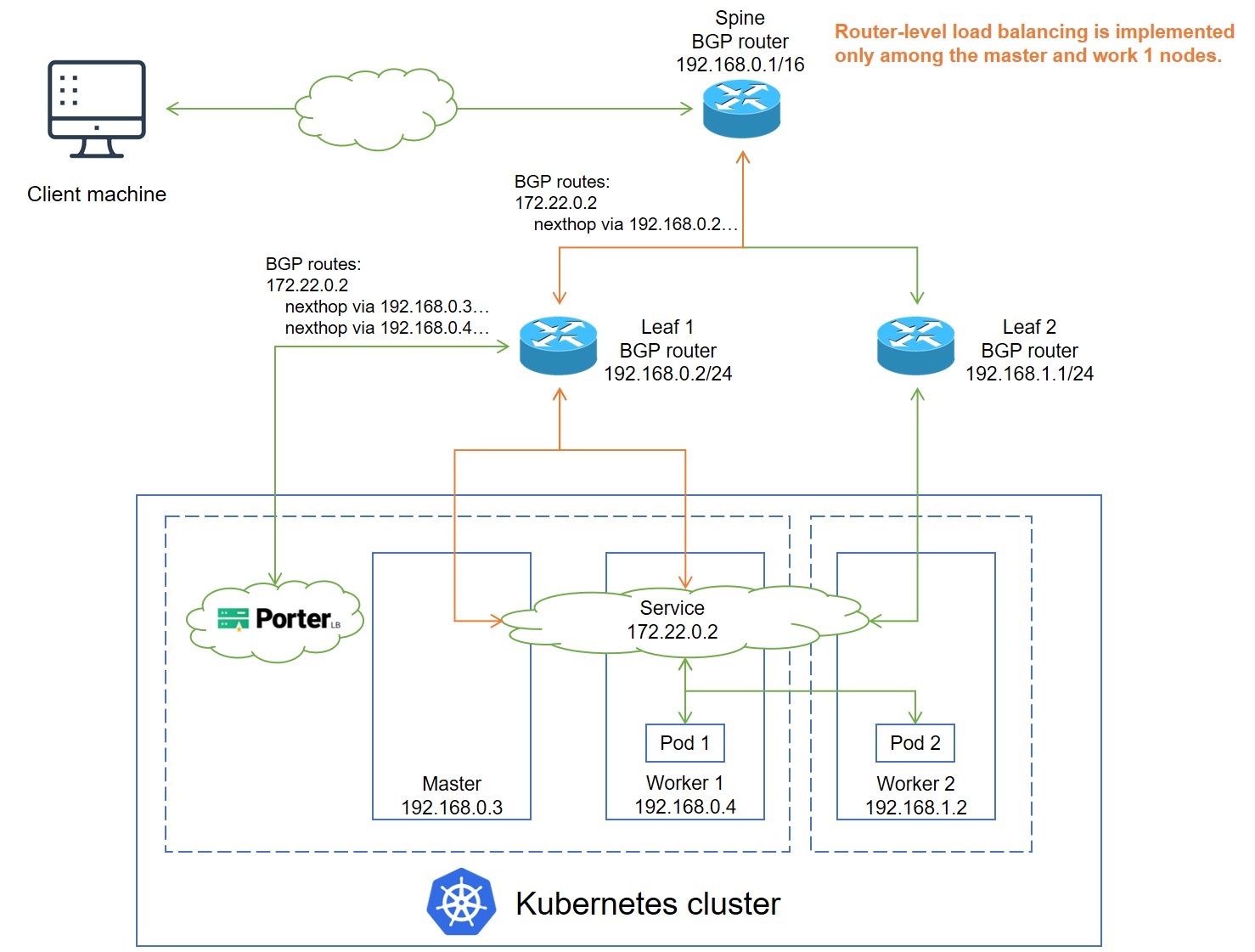
IP addresses in the preceding figure are examples only. The topology is described as follows:
- In the Kubernetes cluster, the master and worker 1 nodes are deployed under the leaf 1 BGP router, and the worker 2 node is deployed under the leaf 2 BGP router. PorterLB is only installed under leaf 1 (by default, only one PorterLB replica is installed).
- A Service backed by two Pods is deployed in the Kubernetes cluster, and is assigned an IP address 172.22.0.2 for external access. Pod 1 and Pod 2 are deployed on worker 1 and worker 2 respectively.
- PorterLB establishes a BGP connection with leaf 1 and publishes the IP addresses of the master node and worker 1 (192.168.0.3 and 192.168.0.4) to leaf 1 as the next hop destined for the Service IP address 172.22.0.2.
- Leaf 1 establishes a BGP connection with the spine BGP router and publishes its own IP address 192.168.0.2 to the spine router as the next hop destined for the Service IP address 172.22.0.2.
- When an external client machine attempts to access the Service, the spine router forwards the Service traffic to leaf 1, and leaf 1 load balances the traffic among the master node and worker 1.
- Although Pod 2 on worker 2 can also be reached over kube-proxy, router-level load balancing is implemented only among the master node and worker 1 and the Service bandwidth is limited to the bandwidth of the master node and worker 1.
To resolve the problem, you need to label the Kubernetes cluster nodes and change the PorterLB Deployment configuration so that PorterLB is installed on nodes under all leaf routers. In addition, you need to specify the spec:nodeSelector:matchLabels field in the BgpPeer configuration so that the PorterLB replicas establish BGP connections with the correct BGP routers.
Network Topology After Configuration
This section describes the configuration result you need to achieve. The following figure shows the network topology of a Kubernetes cluster after the configuration.
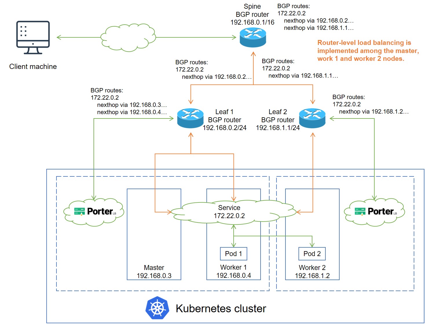
IP addresses in the preceding figure are examples only. The topology is described as follows:
- After the configuration, PorterLB is installed on nodes under all leaf routers.
- In addition to what happens before the configuration, the PorterLB replica installed under leaf 2 also establishes a BGP connection with leaf 2 and publishes the worker 2 IP address 192.168.1.2 to leaf 2 as the next hop destined for the Service IP address 172.22.0.2.
- Leaf 2 establishes a BGP connection with the spine router and publishes its own IP address 192.168.1.1 to the spine router as the next hop destined for the Service IP address 172.22.0.2.
- When an external client machine attempts to access the Service, the spine router load balances the Service traffic among leaf 1 and leaf 2. Leaf 1 load balances the traffic among the master node and worker 1. Leaf 2 forwards the traffic to worker 2. Therefore, the Service traffic is load balanced among all three Kubernetes cluster nodes, and the Service bandwidth of all three nodes can be utilized.
Configuration Procedure
Prerequisites
You need to prepare a Kubernetes cluster where PorterLB has been installed.
Procedure
NOTE
-
Log in to the Kubernetes cluster and run the following commands to label the Kubernetes cluster nodes where PorterLB is to be installed:
kubectl label --overwrite nodes master1 worker-p002 lb.kubesphere.io/v1alpha1=porterNOTE
PorterLB works properly if it is installed on only one node under each leaf router. In this example, PorterLB will be installed on master1 under leaf1 and worker-p002 under leaf2. However, to ensure high availability in a production environment, you are advised to installed PorterLB on at least two nodes under each leaf router. -
Run the following command to scale the number of porter-manager Pods to 0:
kubectl scale deployment porter-manager --replicas=0 -n porter-system -
Run the following command to edit the porter-manager Deployment:
kubectl edit deployment porter-manager -n porter-system -
In the porter-manager Deployment YAML configuration, add the following fields under
spec:template:spec:nodeSelector: kubernetes.io/os: linux lb.kubesphere.io/v1alpha1: porter -
Run the following command to scale the number of porter-manager Pods to the required number (change the number
2to the actual value):kubectl scale deployment porter-manager --replicas=2 -n porter-system -
Run the following command to check whether PorterLB has been installed on the required nodes.
kubectl get po -n porter-system -o wide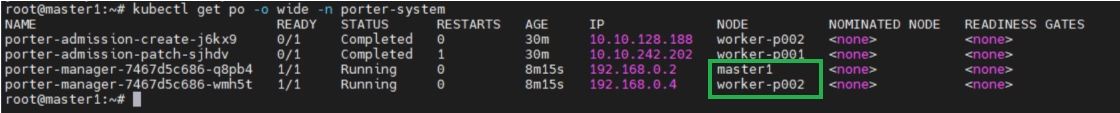
-
Run the following commands to label the Kubernetes cluster nodes so that the PorterLB replicas establish BGP connections with the correct BGP routers.
kubectl label --overwrite nodes master1 porter.kubesphere.io/rack=leaf1kubectl label --overwrite nodes worker-p002 porter.kubesphere.io/rack=leaf2 -
When creating BgpPeer objects, configure the spec:nodeSelector:matchLabels field in the BgpPeer YAML configuration for each leaf router. The following YAML configurations specify that the PorterLB replica on master1 communicates with leaf1, and the PorterLB replica on worker-p002 communicates with leaf2.
# BgpPeer YAML for master1 and leaf1
nodeSelector:
    matchLabels:
      porter.kubesphere.io/rack: leaf1
# BgpPeer YAML for worker-p002 and leaf2 nodeSelector: matchLabels: porter.kubesphere.io/rack: leaf2
Feedback
Was this page helpful?
Glad to hear it! Please tell us how we can improve.
Sorry to hear that. Please tell us how we can improve.